

How to Calculate the Required Clamping Force for an Injection Moulding Machine
Selecting an injection moulding machine with the correct clamping force is essential for stable production, consistent product quality and efficient machine operation.
If the clamping force is too low, the mould may open slightly during injection, causing flash along the parting line. If the selected machine has significantly more clamping force than the application requires, it may increase equipment costs and lead to inefficient machine utilization.
The calculation mainly depends on the total projected area of the moulded parts and runners, together with the estimated cavity pressure during injection. The material, product geometry, mould design and processing conditions must also be considered.
1. What Is Clamping Force?
Clamping force is the force generated by an injection moulding machine's clamping unit to keep the mould closed during the injection and packing stages.
During injection, molten plastic flows into the mould cavity under pressure. This pressure creates a force that pushes the two mould halves apart. The clamping unit must provide sufficient force to resist this separating force and keep the mould securely closed.
The required clamping force is therefore closely related to the projected area of the moulded product and the pressure inside the mould cavity.
2. Understand the Projected Area
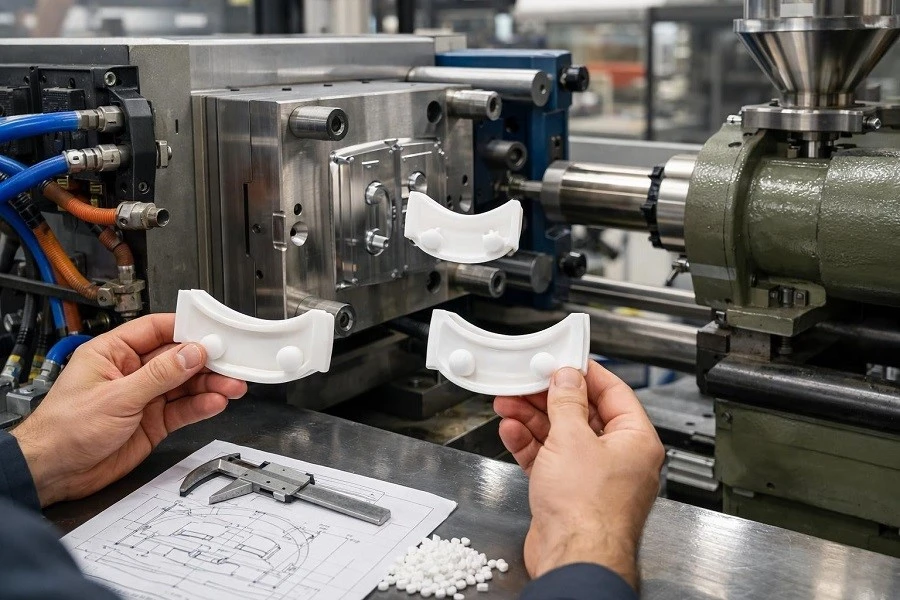
The projected area is the two-dimensional area of the moulded product projected onto the mould's parting plane, viewed in the direction of mould opening. It is not the total surface area of the product.
For machine selection, calculate the projected area of all cavities and include the projected area of the runner system where applicable.
For irregular products, the projected area can be obtained from the product's CAD drawing or estimated using suitable design software.
For multi-cavity moulds, the projected areas of all cavities must be added together.
3. Calculate the Required Clamping Force
The basic relationship is:
Using consistent metric units:
- F = theoretical clamping force in kN
- A = total projected area in mm²
- P = estimated average cavity pressure in MPa
The pressure used in this calculation is the pressure acting inside the mould cavity. It is not the maximum injection pressure listed in the machine specifications.
In practice, the machine selection should also account for process variation, material characteristics, mould design and the manufacturer's recommendations. An appropriate operating margin should be determined with the moulding engineer rather than applying one fixed safety factor to every application.
4. Factors That Affect Clamping Force
Product Geometry & Wall Thickness
Product shape, projected area, wall thickness and flow length influence the pressure required to fill the mould.
Thin-wall products and products with long flow paths may require higher injection pressure.
Plastic Material
Different plastics have different flow characteristics and processing requirements. Viscosity and reinforcement affect pressure.
Glass-fibre-reinforced materials may require different processing conditions.
Number of Cavities & Runners
A multi-cavity mould increases the total projected area. The runner system also contributes and should be included.
Projected area and cavity pressure must be evaluated together.
Mould Design & Conditions
Gate location, runner design, venting, mould temperature and filling speed influence cavity pressure.
Optimized processing helps reduce pressure and improve stability.
5. How to Choose a Machine After Calculating Clamping Force
Once the required clamping force has been estimated, compare it with the available machine models.
However, clamping force alone does not determine whether a machine is suitable.
Also check:
A suitable machine must meet both the clamping requirements and the injection and mould-installation requirements.
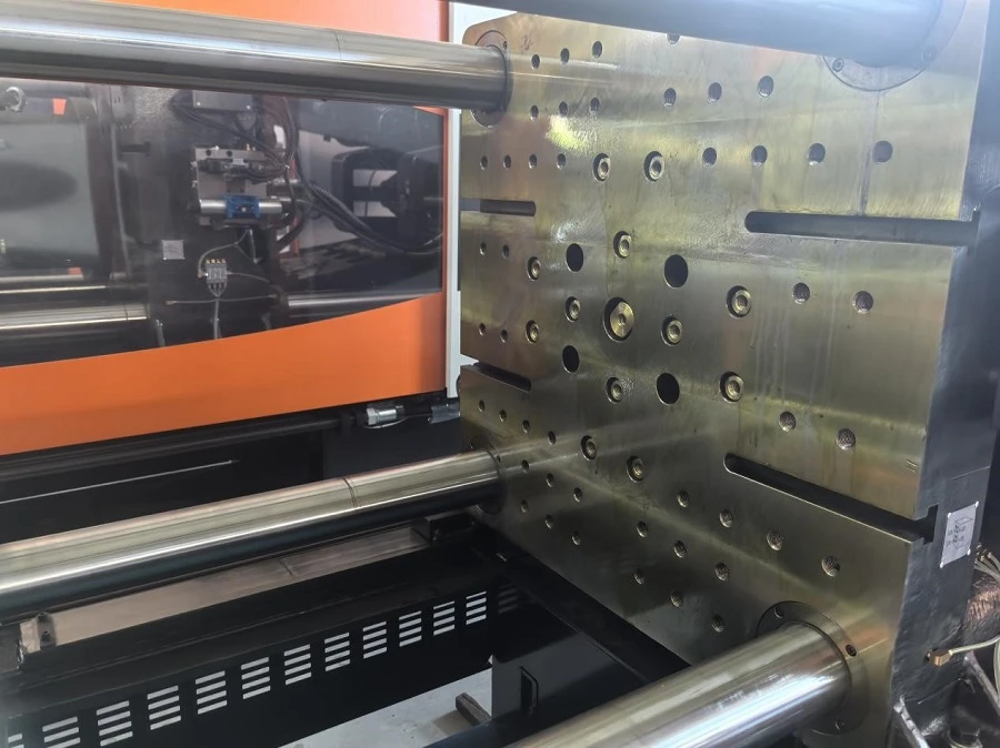
6. Common Mistakes When Selecting Clamping Force
Product weight does not directly determine the required clamping force. Two products with similar weights may have very different projected areas and cavity-pressure requirements.
The projected area of the runner system can contribute to the total separating force. It should not be overlooked when calculating the mould's total projected area.
Machine injection pressure and mould cavity pressure are different measurements. Using max injection pressure directly in the formula can lead to inaccurate results.
A larger machine is not automatically better. Excessive clamping force may increase investment costs and create unnecessary mould loading.
The goal is to select a machine that meets the actual moulding requirements with an appropriate operating margin.
7. Get Help Selecting the Right Injection Moulding Machine
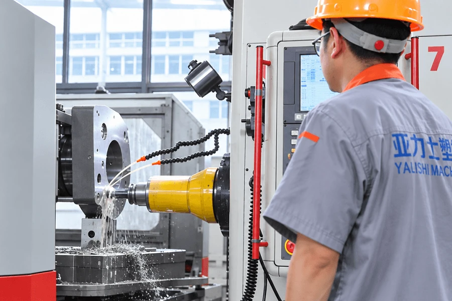
Calculating the required clamping force is an important step in machine selection, but the final decision should consider the complete moulding process.
ARLEX can help evaluate machine suitability based on product information, material requirements, mould dimensions and production targets.
With these details, the required clamping force and other machine specifications can be reviewed together.
Related Guides
Explore more technical guides for injection moulding machine selection.