

Precision Injection Moulding for Electrical and Electronic Components
Electrical and electronic components require consistent dimensions, reliable assembly interfaces, and suitable material performance. From connector housings and terminal blocks to relay bases, sensor housings, and electrical enclosures, each component places different demands on the injection moulding process.
ARLEX provides injection moulding machine solutions for electrical and electronic component manufacturing. Machine selection is based on the component design, resin grade, mould layout, required shot size, clamping force, and production targets.
Electrical & Electronic Component Applications
1. Connectors and Plug Housings
Electrical connectors and plug housings often contain thin walls, multiple pin cavities, locking features, and precise mating surfaces.
Typical applications include:
- Multi-pin connector housings
- Wire connector bodies
- Plug and socket housings
- Automotive and industrial connector components
- Electrical connector clips and retainers
Key moulding considerations:
- Consistent filling of thin walls and narrow sections
- Dimensional accuracy around pin cavities and mating interfaces
- Appropriate injection speed and pressure for the selected resin
- Stable mould temperature and repeatable process conditions
- Suitable injection capacity for the complete multi-cavity shot
Machine configuration should be evaluated together with the mould design, resin flow characteristics, and required production cycle.

2. Terminal Blocks and Electrical Connection Components

Terminal blocks and electrical connection components are used to organize and secure electrical connections in industrial equipment, control panels, and electrical systems.
Typical applications include:
- Terminal block housings
- Terminal carriers
- Relay bases
- Electrical connection supports
- Insulating components for metal contacts
Key moulding considerations:
- Dimensional consistency around terminal mounting positions
- Accurate positioning of metal inserts where insert moulding is required
- Adequate mould protection for delicate cavities and inserts
- Material selection based on electrical, thermal, and mechanical requirements
- Repeatable filling and packing to reduce dimensional variation
3. Electrical Housings and Enclosures
Electrical housings protect internal components and provide mounting, fastening, and assembly interfaces.
Typical applications include:
- Junction boxes
- Circuit breaker housings
- Power supply covers
- Adapter bodies
- Electrical equipment enclosures
- Control system covers
Key moulding considerations:
- Projected area and required clamping force
- Mould dimensions and tie-bar clearance
- Wall thickness and structural rib design
- Screw bosses, clips, and assembly interfaces
- Opening stroke and ejection requirements
- Dimensional stability after moulding

4. Sensor Housings and Technical Components

Sensor and technical components often require compact designs, accurate mounting features, and reliable interfaces with other parts.
Typical applications include:
- Sensor housings
- Coil bobbins
- Coil carriers
- Internal technical supports
- Small electrical component housings
Key moulding considerations:
- Consistent dimensions for assembly and mounting
- Appropriate injection capacity for small or multi-cavity moulds
- Resin compatibility with the intended operating environment
- Controlled filling and packing
- Repeatable process conditions for critical dimensions
Depending on the component design and material, engineering thermoplastics such as PA, PBT, POM, PC/ABS, and LCP may be considered. The final resin should be selected according to the component's actual electrical, thermal, mechanical, and environmental requirements.
5. Metal Insert Moulded Components
Metal insert moulding combines metal components with moulded plastic to create integrated parts.
Typical applications include:
- Threaded insert housings
- Metal contact carriers
- Busbar supports
- Electrical mounting components
- Insert-moulded terminal parts
Key moulding considerations:
- Insert dimensions and positioning method
- Mould structure and insert retention
- Injection pressure and flow direction
- Mould protection and loading safety
- Robot or operator loading requirements
- Repeatability of the finished assembly interface
For automated insert moulding, the production layout may include insert feeding, positioning, moulding, part removal, and inspection. The required automation level depends on insert geometry, production volume, and cycle-time targets.

How to Select the Right Injection Moulding Machine
Selecting an injection moulding machine for electrical components requires more than checking the required tonnage. The injection unit, clamping unit, mould, material, and production process must work together.
1. Calculate the Required Clamping Force
Clamping force should be evaluated according to the total projected area of the moulded parts and runner system, together with the estimated cavity pressure.
Important information includes:
- Component projected area
- Number of cavities
- Runner layout
- Resin characteristics
- Expected cavity pressure
- Mould design and process conditions
Small electrical components may use multi-cavity moulds. Although each component is lightweight, the total projected area can create a significant clamping-force requirement. Do not select the machine based on component weight alone. The final clamping-force requirement should be confirmed using mould and process data.

2. Match Injection Capacity to the Complete Shot

Injection capacity should be matched to the total shot, including all moulded components in one cycle, runner and sprue material where applicable, the selected resin, and required filling and packing conditions.
Machine injection-weight specifications are commonly specified using a reference material such as polystyrene. Actual shot capacity can differ depending on resin density and processing characteristics.
An injection unit that is too large for the required shot may increase material residence time and make process control more difficult. An injection unit that is too small may limit the required shot size or production rate. The appropriate injection unit should be selected using the actual resin grade and complete shot requirement.
3. Choose the Appropriate Screw Diameter and Plasticizing Capacity
Screw diameter influences injection volume, injection performance, and plasticizing behaviour. For electrical and electronic components, the screw configuration should be considered in relation to:
- Required shot size
- Resin viscosity and flow characteristics
- Glass-fibre content
- Flame-retardant additives
- Required injection speed and pressure
- Plasticizing recovery time
- Material sensitivity and processing temperature
For glass-fibre-reinforced or other abrasive materials, screw and barrel wear resistance should be evaluated according to the resin formulation and production conditions. A larger screw is not automatically better. The objective is to match injection performance and plasticizing capacity to the actual production requirements.
4. Check Mould Dimensions and Opening Requirements
The machine must accommodate the complete mould, not just the finished component. Check:
- Tie-bar spacing
- Platen dimensions
- Minimum and maximum mould height
- Mould weight and platen loading
- Required opening stroke
- Available daylight
- Ejector stroke and force
- Robot access and takeout space
For electrical enclosures and larger housings, mould dimensions may determine the required machine size before injection capacity is considered.

5. Evaluate Material and Processing Requirements
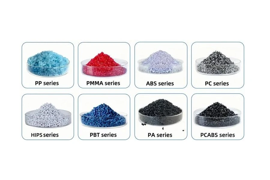
Electrical and electronic components may use different engineering thermoplastics depending on their intended application. Material selection may consider:
- Electrical insulation requirements
- Heat resistance
- Mechanical strength
- Impact performance
- Dimensional stability
- Flame-retardant requirements
- Glass-fibre reinforcement
- Surface appearance
- Moisture sensitivity and drying requirements
For example, PA, PBT, PC/ABS, POM, and LCP may be used in different technical applications, but they are not interchangeable. The final resin grade must be confirmed against the component specification and operating environment. The injection moulding machine and screw configuration should then be matched to the selected material.
6. Consider Automation and Production Cycle
For high-volume electrical component production, automation may help improve handling consistency and reduce manual intervention. Depending on the project, the production cell may include:
- Insert loading
- Robot part removal
- Conveyor transfer
- Component separation
- Visual inspection
- Automatic counting and collection
Cycle time depends on injection, packing, cooling, plasticizing recovery, mould movement, and part removal. Automation should be evaluated according to the mould structure, component geometry, production volume, and required cycle time. A robot or automated insert-loading system should not be selected independently of the mould and machine layout.
Common Machine Selection Mistakes
Selecting by Part Weight Only
A lightweight component may require considerable clamping force when produced in a multi-cavity mould or when its projected area is large.
Choosing an Oversized Injection Unit
An injection unit that is unnecessarily large may result in an unsuitable shot-to-barrel ratio and longer material residence time. Match the unit to the actual shot size and resin.
Ignoring Glass-Fibre and Flame-Retardant Materials
Material additives can influence flow, wear, processing conditions, and moulding performance. Screw and barrel selection should be based on the specific resin formulation.
Overlooking Insert Moulding Requirements
Metal inserts require suitable positioning, retention, mould protection, and loading arrangements. These requirements should be confirmed before machine and automation selection.
Checking Tonnage but Not Mould Compatibility
A machine may have sufficient clamping force but still be unsuitable because of tie-bar spacing, mould height, opening stroke, ejector requirements, or robot access.
ARLEX Machine Selection for Electrical & Electronic Components
ARLEX evaluates electrical and electronic component projects according to the complete production requirement. Our machine recommendation process considers:
The final machine configuration should be confirmed according to the actual component drawing, mould design, resin specification, and production target.
What Information Should You Prepare?
To help evaluate your electrical or electronic component project, please provide:
Component information
- Component drawing or sample
- Overall dimensions and critical features
- Material grade and colour
- Required dimensional tolerances
- Intended application
Mould information
- Mould dimensions
- Number of cavities
- Runner or hot-runner arrangement
- Total shot weight
- Insert details, if applicable
Production requirements
- Target output
- Required cycle time
- Automation requirements
- Existing machine information, if replacing or upgrading equipment
With these details, ARLEX can evaluate the suitable machine size, injection unit, clamping unit, and potential automation arrangement for your project.
Request an Electrical Component Machine Recommendation
Planning a new electrical component moulding project or upgrading an existing production line? Send ARLEX your component drawings, resin grade, mould specifications, cavity count, and production target. Our team can review the requirements and recommend a suitable injection moulding machine configuration.
Get a Machine Recommendation