


Reinforced cast iron construction and advanced closed-loop control ensure smooth rotation, accurate positioning, stable operation, and extended mold service life.
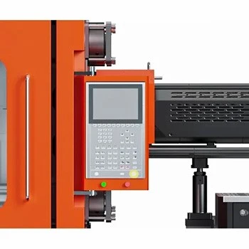
High-performance controller with synchronized communication, remote monitoring, precise positioning, and integrated system management for stable, accurate, and efficient multi-component molding.

Modular injection configurations, specialized screw technology, dual-cylinder balancing, and adaptive temperature control ensure maximum flexibility, precision, and reliable molding performance.
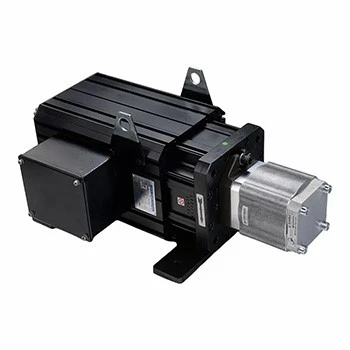
High-precision closed-loop servo control delivers accurate flow and pressure regulation, stable molding performance, and up to 80% energy savings.
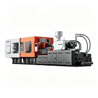
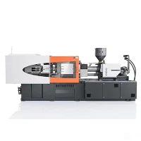
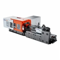
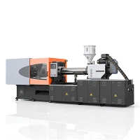

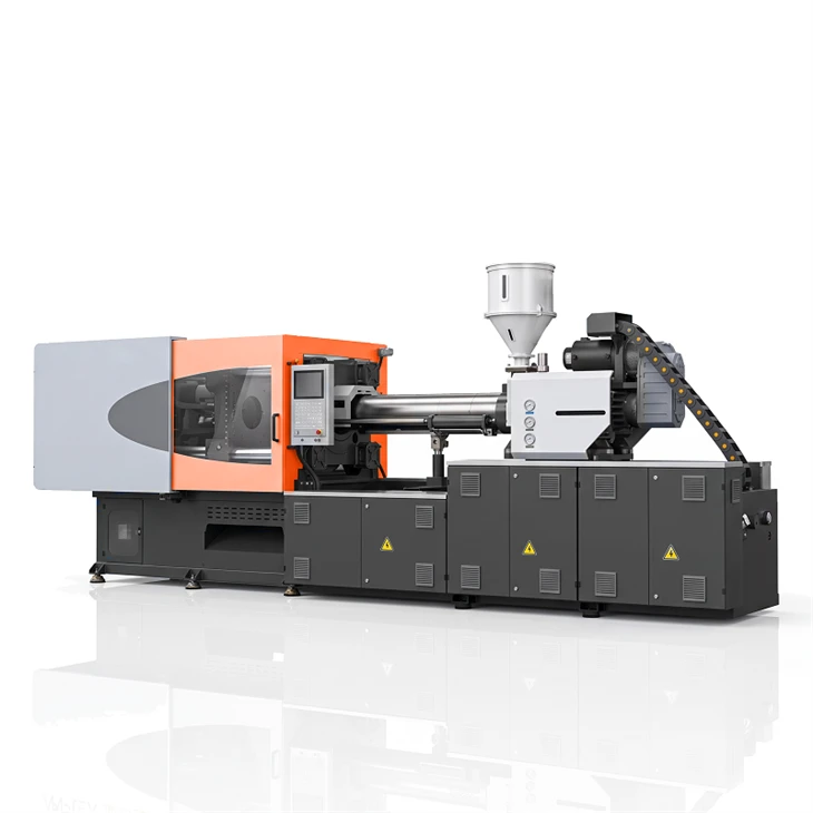
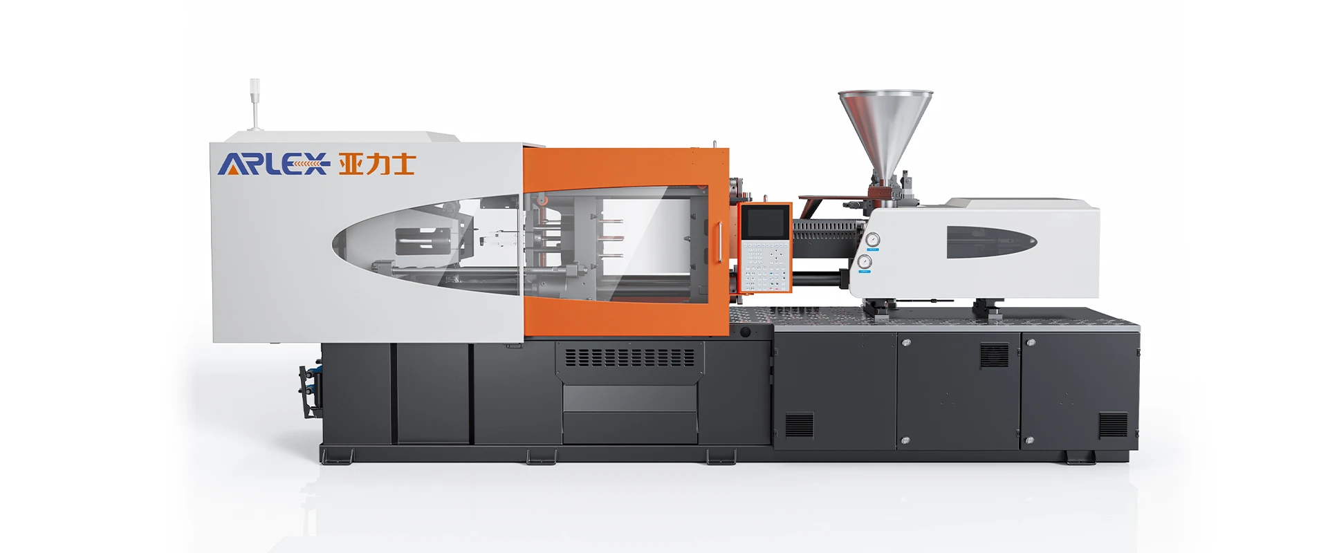
Servo-Hydraulic Multi-Cavity Molding Machine
Ningbo Yalishi(Arlex) Plastic Machinery Co., Ltd. is one of the leading manufacturers and suppliers of servo-hydraulic multi-cavity molding machine in China. Please feel free to wholesale advanced servo-hydraulic multi-cavity molding machine made in China here from our factory.
The Servo-Hydraulic Multi-Cavity Molding Machine combines fast-response servo motor drives with optimized hydraulic oil distribution to deliver uniform clamp force, repetitive injection volume control, and continuous resin plasticizing for multi-cavity tooling operations.
Servo-Hydraulic System
Servo Motor: Permanent magnet synchronous drive adjusts pump rotational speed based on real-time system torque demand, eliminating power bypass during cooling phases.
Hydraulic System: Integrated manifold blocks reduce piping length and flow resistance, maintaining fluid turbulence at lower levels during continuous cycling.
Closed-Loop Control: Pressure sensors and optical encoders continuously feed system signals back to the main controller to compensate for fluid thermal expansion.
Pressure Control: Proportional pressure regulation holds dynamic line pressure variations within ±0.5 bar to limit parting line flash across mold cavities.
Speed Control: Variable displacement control executes pre-set acceleration and deceleration curves to reduce hydraulic pressure spikes.
Response and Stability: System drive acceleration reaches target operating pressure in 50 ms while holding oil circuit temperature under 45°C under continuous load.
Clamping Unit
Clamping Force: Five-point twin-toggle mechanical structure transfers clamping load evenly across the platen area to reduce center deflection.
Platen Structure: Cast iron box platens dimensioned via Finite Element Analysis maintain structural rigidity under maximum tonnage.
Tie-Bar Spacing: Extended distance between tie-bars accommodates wide-body multi-cavity mold bases and auxiliary core-pulling fluid lines.
Mold Height: Motorized die-height adjustment uses synchronized ring gears to maintain platen alignment during mold setup routines.
Mold Installation: Standardized T-slots and mounting hole patterns simplify mold alignment and support standard quick-change systems.
Clamping Stability: Precision platen guide tracks support moving platen weight, maintaining parallel movement within 0.05 mm across the entire stroke.
Injection Unit
Injection Speed: Managed oil delivery speed supports controlled melt front advancement in multi-cavity filling without localized gate freeze.
Injection Pressure: Multi-stage pressure delivery achieves up to 2200 bar to pack tight-tolerance mold cavities along extended runner systems.
Injection Stroke: Optical linear transducers track screw position with 0.1 mm resolution for consistent volume delivery per cycle.
Screw Diameter: Bimetallic screws in application-specific geometries manage shear heat and melt uniformity across specified resin grades.
Injection Weight: Measured shot-to-shot weight variation stays below 0.2% over consecutive production cycles.
Plasticizing Capability: Continuous hydraulic motor torque maintains screw rotation speed during cooling cycles.
Control & Process Stability
Injection Pressure and Speed Control: Controller executes 10-stage velocity curves and 5-stage holding pressure steps per program settings.
Multi-Stage Injection: Position, pressure, or time-based V/P switchover points control cavity fill transitions and limit mechanical stress.
Temperature Control: Multi-zone PID heating modules maintain barrel temperatures within ±1°C using solid-state relays.
Back-Pressure Control: Digital back-pressure adjustments maintain uniform melt density and evacuate entrained gas during screw recovery.
Repeatability: High-speed signal processors sample machine feedback every millisecond to enforce cycle consistency.
Recommended Materials
PP: Polypropylene for high-cavity closures, container caps, and thin-wall packaging.
PE: Polyethylene for high-volume threaded lids, industrial caps, and household closures.
ABS: Acrylonitrile Butadiene Styrene for multi-cavity electrical housing parts and structural components.
PC: Polycarbonate for clear housings, optical-grade elements, and electrical connectors.
PA: Polyamide for industrial fasteners, clips, and mechanical components requiring thermal tolerance.
POM: Polyacetal for small gears, sliding elements, and precision mechanical subassemblies.
Recommended Applications
Threaded Closures & Lids: Suitable for high-cavity molds requiring consistent holding pressure to maintain thread geometry.
Thin-Wall Packaging Containers: Applied in high-velocity fill setups requiring precise V/P switchover control.
Automotive Fasteners & Clips: Used for multi-cavity molds requiring stable ejector force and core-pulling synchronization.
Electrical Terminal Blocks: Suitable for small-shot multi-cavity tooling demanding precise injection stroke repeatability.
Industrial Pipe Fittings: Applied in heavy-wall multi-cavity setups requiring extended holding pressure stability
Recommended Machine Models
This configuration can be applied across selected general-purpose injection molding machines: 90T / 120T / 140T / 158T / 178T / 218T / 278T / 318T / 358T / 408T / 478T / 568T / 658T / 788T / 988T / 1180T / 1380T / 1680T
Machine Configuration
|
Specification Parameter |
Unit |
Small Tonnage Range (90T - 218T) |
Medium Tonnage Range (278T - 568T) |
Large Tonnage Range (658T - 1680T) |
|
Clamping Force |
kN |
900 - 2180 |
2780 - 5680 |
6580 - 16800 |
|
Tie-Bar Distance (H×V) |
mm |
360×360 - 530×530 |
580×580 - 830×830 |
920×920 - 1400×1400 |
|
Platen Size (H×V) |
mm |
530×530 - 780×780 |
860×860 - 1220×1220 |
1350×1350 - 2000×2000 |
|
Max Mold Stroke |
mm |
320 - 480 |
530 - 820 |
900 - 1450 |
|
Mold Height Range (Min-Max) |
mm |
150-450 / 180-520 |
200-600 / 300-800 |
350-950 / 500-1300 |
|
Ejector Stroke |
mm |
100 - 150 |
160 - 220 |
250 - 380 |
|
Ejector Force |
kN |
33 - 58 |
77 - 140 |
180 - 320 |
|
Screw Diameter |
mm |
30 - 50 |
50 - 85 |
85 - 140 |
|
Theoretical Shot Volume |
cm³ |
110 - 450 |
490 - 2250 |
2500 - 11500 |
|
Injection Weight (PS) |
g |
100 - 410 |
445 - 2040 |
2270 - 10400 |
|
Max Injection Pressure |
bar |
1650 - 2200 |
1600 - 2100 |
1500 - 1950 |
|
Servo Motor Power |
kW |
11 - 22 |
30 - 55 |
65 - 130 |
|
Heating Capacity |
kW |
7.0 - 14.5 |
16.5 - 35.0 |
40.0 - 95.0 |
Quality Testing & Technical Support
Quality Verification Standards
- Platen Parallelism Testing: Laser measurements verify platen alignment under zero load and full clamping force before factory release.
- Pressure Retention Monitoring: Static pressure hold tests confirm zero internal valve bypass across hydraulic manifold circuits.
- Thermal Inspection: Infrared thermography tracks heat distribution in hydraulic lines and electrical control enclosures under continuous operation.
- Kinematic Dry Run: Continuous 100,000-cycle dry run testing verifies mechanical movement stability prior to shipment.
- Shot Weight Sampling: Part weight sampling across test molds verifies standard deviation limits over consecutive production cycles.
Technical Support Capabilities
- Tooling Compatibility Review: Verification of platen dimensions, ejector pin layouts, and core-pull interfaces relative to required tonnage.
- Process Parameter Guidance: Technical assistance in setting baseline pressure, speed, and barrel temperature profiles.
- Spare Parts Availability: Supply of replacement hydraulic seals, position transducers, heating bands, and electronic control boards.
- Commissioning Documentation: Factory Acceptance Test records and installation setup diagrams provided upon delivery.
fAQ
Q: How does this machine maintain consistent clamp force across multi-cavity tooling?
A: Clamp force stability is achieved through rigid platens designed via Finite Element Analysis, combined with closed-loop pressure control. This limits platen flexing and maintains clamping force across the mold parting line.
Q: How does the servo drive system reduce power consumption?
A: The servo motor adjusts pump rotation based on real-time flow demand. During holding and cooling phases, motor speed decreases, lowering power consumption compared to fixed-displacement pump systems.
Q: Can the control system integrate auxiliary hydraulic core pulls?
A: Yes. The controller includes programmable core-pulling routines synchronized with clamping movement, ejector signals, or injection stroke position.
Q: How is hydraulic fluid temperature maintained during continuous production?
A: Because the servo motor operates only during active fluid demand, heat generation is minimized. An integrated heat exchanger maintains fluid operating temperatures below 45°C.
Q: What screw options are available for processing abrasive materials?
A: Bimetallic barrels and hardened alloy screws are available to handle glass-filled or flame-retardant resins, protecting components against mechanical wear.
Hot Tags: servo-hydraulic multi-cavity molding machine, China servo-hydraulic multi-cavity molding machine manufacturers, suppliers, factory
You Might Also Like


Send Inquiry