


Reinforced cast iron construction and advanced closed-loop control ensure smooth rotation, accurate positioning, stable operation, and extended mold service life.
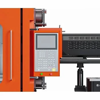
High-performance controller with synchronized communication, remote monitoring, precise positioning, and integrated system management for stable, accurate, and efficient multi-component molding.

Modular injection configurations, specialized screw technology, dual-cylinder balancing, and adaptive temperature control ensure maximum flexibility, precision, and reliable molding performance.
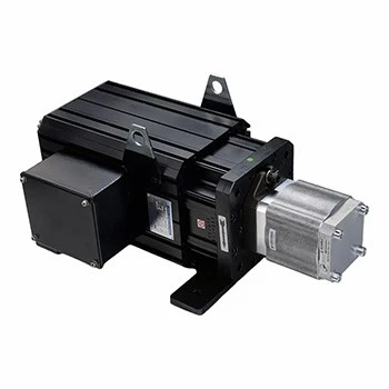
High-precision closed-loop servo control delivers accurate flow and pressure regulation, stable molding performance, and up to 80% energy savings.
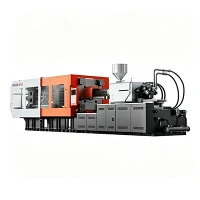
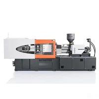
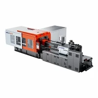
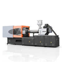


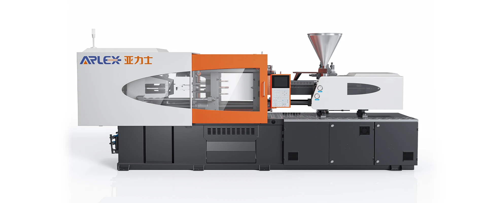
Low-Energy Servo Molding Machine
Ningbo Yalishi(Arlex) Plastic Machinery Co., Ltd. is one of the leading manufacturers and suppliers of low-energy servo molding machine in China. Please feel free to wholesale advanced low-energy servo molding machine made in China here from our factory.
The Low-Energy Servo Molding Machine combines dynamic servo pump technology with precise hydraulic energy management to minimize electrical power draw across continuous manufacturing cycles.
What Makes an Injection Molding Machine Energy Efficient?
Servo Drive: Regulates motor rotation speed in direct proportion to real-time flow and pressure setpoints, replacing constant-speed induction motors.
Hydraulic Demand: Matches hydraulic fluid displacement to active mechanical motions, removing continuous high-volume oil bypass.
Pump Control: Uses closed-loop encoder feedback to adjust system delivery within milliseconds based on control pressure and velocity inputs.
Idle Operation: Lowers motor speed down to minimal levels during non-action phases, reducing baseline electrical draw.
Injection Cycle: Modulates pressure and flow dynamically at every distinct phase to eliminate throttled fluid power losses.
Holding Pressure: Maintains high system pressure at lower motor rotation speed, consuming only the energy required to offset internal hydraulic leakage.
Plasticizing: Optimizes screw torque output and hydraulic motor load, aligning mechanical power draw with resin melt viscosity demands.
Cooling Requirements: Reduces hydraulic oil thermal buildup, decreasing the electrical cooling load imposed on plant fluid chillers.
Servo-Driven Hydraulic System
A variable-speed AC servo motor coupled with an internal gear pump forms the core power unit. Unlike conventional systems where surplus oil continuously bypasses through relief valves at full pressure, the servo motor speed tracks exact machine flow demand.
During high-flow movements such as clamp action or high-speed injection, the servo motor accelerates to deliver exact required displacement. During holding pressure, the motor slows down to maintain pressure setpoints without generating excess oil heat. During cooling and part drop phases, the motor enters a low speed idle state, maintaining pressure readiness while drawing minimal current.
Energy Use During the Injection Cycle
Clamping: High hydraulic flow during rapid traverse; low energy draw during low-pressure mold protection lockup.
Injection: Peak power phase where the servo drive delivers combined maximum flow and target injection pressure.
Holding: Constant pressure demand with minimal oil volume movement; motor speed decreases to reduce electricity consumption.
Plasticizing: Screw rotation demands proportional torque output based on resin type, converting electrical energy into uniform melt shear heat.
Mold Opening: Moderate power draw matched to proportional valve opening speeds and acceleration profiles.
Ejection: Intermittent power delivery matched to mechanical ejector pin actuation forces.
Injection & Plasticizing Efficiency
Linear position sensors on the clamping and injection units send positional data to the controller at microsecond intervals. The vector drive system recalculates motor torque parameters to remove pressure overshoot, pressure spikes, and structural mechanical vibration.
Optimized screw geometry enhances thermal conversion from barrel heater bands while maintaining melt homogeneity. Nitrided barrels paired with bimetallic screw flights maintain consistent volumetric delivery over extended production runs, preventing backflow during injection.
Production Output & Energy Efficiency
Specific energy consumption is evaluated as electrical power consumed per kilogram of processed material (kWh/kg). Evaluating electrical input without accounting for cycle time, part mass, resin viscosity, and mold cavity count leads to inaccurate performance estimates.
A shorter machine cycle time increases throughput per hour, reducing fixed baseline power overhead per unit part. Evaluating machine output alongside measured power draw provides a reliable metric for actual factory floor operating expenses.
Suitable Materials
- Polypropylene (PP)
- Polyethylene (HDPE / LDPE)
- Polystyrene (GPPS / HIPS)
- Acrylonitrile Butadiene Styrene (ABS)
- Polyamide (PA6 / PA66)
- Polycarbonate (PC)
- Polyoxymethylene (POM)
Suitable Applications
Door panel clips, interior trim pieces, engine covers, air vents.
Pipe fittings, terminal housings, gear housings, junction boxes.
Storage containers, furniture fittings, appliance housings, tool handles.
Caps, closures, containers, bucket lids.
Recommended Machine Models
|
Parameter |
Unit |
Model AR-160S |
Model AR-260S |
Model AR-380S |
|
Clamping Force |
kN |
1,600 |
2,600 |
3,800 |
|
Tie Bar Spacing (H×V) |
mm |
460 × 460 |
580 × 580 |
710 × 710 |
|
Platen Dimensions (H×V) |
mm |
680 × 680 |
850 × 850 |
1,030 × 1,030 |
|
Max. Daylight |
mm |
900 |
1,120 |
1,380 |
|
Opening Stroke |
mm |
440 |
540 |
670 |
|
Screw Diameter |
mm |
45 |
55 |
65 |
|
Theoretical Shot Volume |
cm³ |
318 |
582 |
1,028 |
|
Injection Weight (PS) |
g |
290 |
530 |
935 |
|
Injection Pressure |
bar |
1,780 |
1,850 |
1,750 |
|
Servo Motor Power |
kW |
18.5 |
30.0 |
45.0 |
Energy Efficiency Evaluation
To receive a detailed energy consumption comparison and baseline analysis, provide the following operational inputs:
Part Weight: Net component mass and runner weight per shot in grams.
Cycle Time: Total mold cycle duration in seconds.
Material: Polymer resin type and melt flow rate.
Machine Size: Required clamping force in kN and tie bar clearance.
Production Hours: Scheduled daily operating hours and shift patterns.
Annual Production: Target annual unit volume.
Existing Machine Data: Motor type, nameplate kW rating, and measured average running current.
Engineering staff analyze provided site metrics through simulation software to calculate current vs. proposed energy consumption figures based on plant power utility rates.
Testing & Technical Support
Power Metering Verification: Energy consumption recorded via calibrated power meters during continuous dry runs and mold testing.
Melt Temperature Monitoring: Thermal imaging verifies heat distribution across barrel zones and mold cavities.
Hydraulic Pressure Trace: Oscilloscope logs monitor pressure response times, overshoot levels, and hold stability.
Dry Cycle Timing: Laser sensor detection confirms dry cycle speed compliance under standardized test cycles.
Factory Acceptance Testing: Full mold mounting, dry running tests under target cycle parameters, and real-time power data logged before shipping clearance.
Remote Diagnostic Support: System controllers connect directly to diagnostic software to assist technical teams with parameter adjustments and system maintenance.
FAQ
Q: How does a servo hydraulic molding machine reduce energy use compared to traditional machines?
A: Traditional hydraulic systems use fixed-speed induction motors that constantly circulate hydraulic oil at full output, returning unused fluid back to the reservoir. A servo hydraulic machine continuously adjusts motor rotation speed and pump displacement in direct response to pressure and velocity setpoints, eliminating fluid bypass during holding, cooling, and idle phases.
Q: Does energy-efficient operation compromise injection speed or machine response time?
A: No. The AC servo motor accelerates from zero to maximum output speed in under 50 milliseconds. Closed-loop encoder feedback allows immediate pressure and flow adjustments, maintaining fast response times throughout every stroke phase.
Q: How does reduced hydraulic fluid heat generation benefit facility operating costs?
A: When oil passes through relief valves under high pressure, mechanical energy converts into heat. By outputting only the oil volume required for each movement, fluid operating temperature stays lower. This decreases oil cooling water consumption, extends seal life, delays fluid oxidation, and lowers chiller loads.
Q: Can existing mold tooling be mounted without modifications?
A: Yes. Standard molds align with standardized platen layouts, ejector patterns, and locating ring dimensions. Machine settings such as clamp tonnage, injection pressure profiles, and barrel temperatures are configured via the digital touchscreen control interface.
Q: What documentation is supplied for energy verification?
A: Each machine includes factory testing reports containing logged power draw records, hydraulic pressure traces, calibration documentation for temperature controllers, and electrical circuit schematics.
Hot Tags: low-energy servo molding machine, China low-energy servo molding machine manufacturers, suppliers, factory
You Might Also Like


Send Inquiry