


Reinforced cast iron construction and advanced closed-loop control ensure smooth rotation, accurate positioning, stable operation, and extended mold service life.
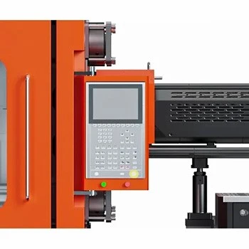
High-performance controller with synchronized communication, remote monitoring, precise positioning, and integrated system management for stable, accurate, and efficient multi-component molding.

Modular injection configurations, specialized screw technology, dual-cylinder balancing, and adaptive temperature control ensure maximum flexibility, precision, and reliable molding performance.
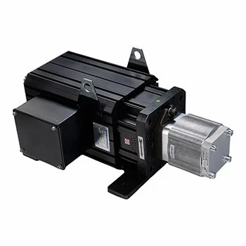
High-precision closed-loop servo control delivers accurate flow and pressure regulation, stable molding performance, and up to 80% energy savings.
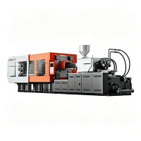
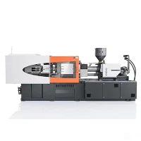
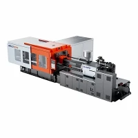
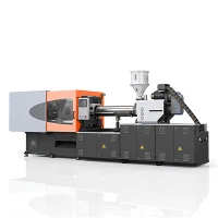


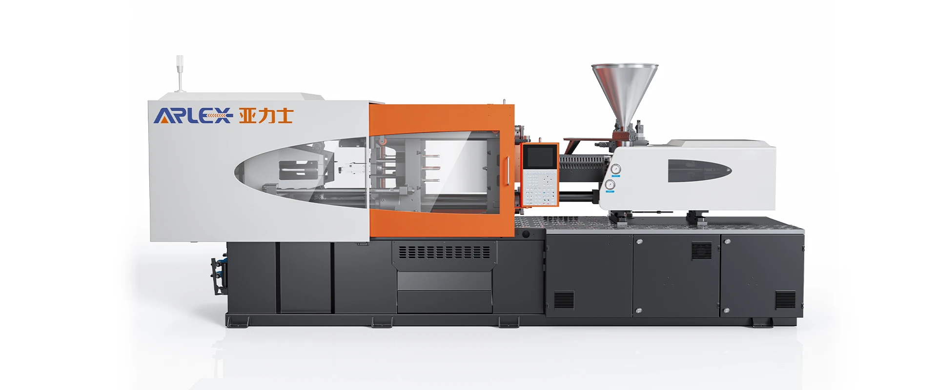
Servo-Hydraulic Energy-Saving Plastic Molding Machine
Ningbo Yalishi(Arlex) Plastic Machinery Co., Ltd. is one of the leading manufacturers and suppliers of servo-hydraulic energy-saving plastic molding machine in China. Please feel free to wholesale advanced servo-hydraulic energy-saving plastic molding machine made in China here from our factory.
The Servo-Hydraulic Energy-Saving Plastic Molding Machine combines permanent magnet motor technology with high-response internal gear pumps to regulate hydraulic fluid delivery according to realtime mechanical load. Engineered for general-purpose plastic manufacturing, this machine stabilizes system oil temperature, reduces factory electrical demand, and maintains shot-to-shot repeating precision across continuous production schedules.
What Makes an Injection Molding Machine Energy Efficient?
Energy reduction in modern hydraulic processing relies on matching power output strictly to system pressure and flow requirements during each phase of the cycle:
Servo Drive: Replaces fixed-speed induction motors with permanent magnet synchronous motors, adjusting motor velocity within milliseconds to meet instant demand.
Hydraulic Demand: Scales fluid displacement according to closed-loop encoder signals, preventing excess oil from dumping through pressure relief valves.
Pump Control: Uses dynamic vector control to adjust pump shaft RPM, eliminating throttling losses across internal valve manifolds.
Idle Operation: Reduces motor speed to near zero during cooling and part handling, lowering idle electrical draw below 5% of peak power rating.
Injection Cycle: Matches motor torque directly to cavity filling resistance, preventing kinetic energy loss under high-pressure conditions.
Holding Pressure: Maintains target holding pressure at low motor RPM, drawing only enough power to offset internal valve leakage.
Plasticizing: Optimizes hydraulic motor speed and screw torque based on melt viscosity requirements of the processed resin.
Cooling Requirements: Reduces hydraulic fluid heat generation, decreasing the thermal load placed on factory cooling towers and oil chillers.
Servo-Driven Hydraulic System
The servo-driven hydraulic system operates through integrated pressure and flow feedback loops. Rather than running a fixed pump at continuous speed and bypassing idle oil, the system recalculates motor RPM based on main manifold pressure transducer readings.
During high-flow movements like fast mold clamping or rapid injection, the motor accelerates immediately to maximum operating speed. When pressure ramps up during clamping lockup or packing, motor torque increases while rotational speed drops to the exact rate needed to maintain force. Because electrical power draw directly follows shaft torque and motor speed, eliminating hydraulic bypass converts power into clean mechanical output without generating fluid friction heat.
Energy Use During the Injection Cycle
Hydraulic loads vary significantly through each mechanical phase of the molding process:
Clamping Phase
High oil volume moves the platen quickly during traverse, followed by rapid motor torque scaling for mechanical toggle lockup.
Injection Phase
Peak flow and pressure push polymer melt into mold cavities. The servo motor operates at maximum dynamic response to maintain programmed injection speed.
Holding Phase
System pressure remains high while fluid movement drops near zero. The motor maintains force at low RPM with minimal power draw.
Plasticizing Phase
The hydraulic motor rotates the screw to melt incoming resin. Power consumption stabilizes based on screw geometry, backpressure settings, and material viscosity.
Mold Opening Phase
Moderate flow breaks mold parting lines and moves the platen smoothly to the end position.
Ejection Phase
Low hydraulic load actuates mechanical knockouts or core-pull cylinders at reduced motor RPM.
Injection & Plasticizing Efficiency
Melt quality and energy consumption depend heavily on screw control and thermal insulation:
|
Process Parameter |
Efficiency Impact |
Engineering Mechanism |
|
Screw L/D Ratio |
Homogeneous melt preparation |
Standard 20:1 to 22:1 L/D geometry fully plasticizes resin without excessive rotational drag. |
|
Backpressure Control |
Consistent melt density |
Proportional control prevents void formation while keeping screw torque within efficient operating limits. |
|
Injection Response |
Reduced filling time |
Closed-loop speed transitions prevent pressure spikes and smooth out power draw. |
|
Barrel Heating |
Reduced thermal loss |
Multi-zone ceramic heaters with insulating covers direct heat into the barrel rather than ambient air. |
Production Output & Energy Efficiency
Energy performance must be measured by specific power consumption-expressed as electrical power used per kilogram of resin processed (kWh/kg)-rather than static idle ratings or isolated percentages.
Actual power draw depends on key manufacturing factors:
Part Wall Thickness: Thicker parts extend cooling times, lengthening the low-power phase where servo systems save the most electricity compared to standard pumps.
Cycle Speed: Fast production cycles demand quick dynamic response (under 50ms to reach maximum flow) to prevent cycle delay while maintaining pressure consistency.
Material Properties: Standard resins (PP, PE) process at lower temperatures and pressures than engineering polymers (PA, PC), directly altering motor torque loads.
Mold & Runner Layout: Optimized runner sizing reduces cavity resistance, allowing lower operating pressure and lower power draw.
Evaluating power draw on a kWh/kg basis provides realistic operating cost calculations tailored to specific production setups.
Suitable Materials
The injection unit handles standard commodity polymers and reinforced engineering resins:
|
Polyolefins |
Polypropylene (PP), High/Low-Density Polyethylene (HDPE/LDPE) |
|
Styrenics |
Polystyrene (GPPS/HIPS), Acrylonitrile Butadiene Styrene (ABS) |
|
Engineering Resins |
Polyamide (PA6/PA66), Polycarbonate (PC), Polyoxymethylene (POM) |
|
Blends |
PC/ABS alloys, modified PPE compounds |
|
Reinforced Polymers |
Glass-fiber filled resins up to 30% content using wear-resistant barrel assemblies |
Suitable Applications
Automotive Components
Interior clips, door handle brackets, housing covers, structural brackets.
Consumer Appliances
Power tool casings, washing machine components, electronic enclosures.
Industrial Goods
Heavy-duty storage crates, totes, pipe fittings, electrical junction boxes.
Household Items
Storage containers, kitchenware, furniture fittings, cap closures.
Equipment Enclosures
Structural device covers, equipment frames, non-diagnostic housings.
Energy Efficiency Evaluation
Accurate power draw projections require comparing actual production data against baseline equipment specs:
Required Technical Inputs for Assessment:
Part Specifications: Net part weight and runner system weight per shot.
Cycle Profile: Mold-to-mold cycle time broken down by cooling, holding, and injection durations.
Resin Data: Specific polymer grade, melt flow index, and processing temperatures.
Machine Size: Clamping tonnage and injection volume currently used for the target mold.
Operating Hours: Annual operating schedule (e.g., continuous 24/7 duty, 6,000 hours per year).
Baseline Power Data: Current motor kilowatt rating, measured hourly power draw, and oil cooling water usage.
Submitting these operational metrics allows technical personnel to model specific energy consumption (kWh/kg), compare running costs, and calculate payback timelines based on local electricity rates.
Testing & Technical Support
Factory verification procedures ensure consistent operational performance prior to delivery:
Hydraulic Pressure Inspection: 24-hour pressure holding tests to verify manifold sealing and line integrity at maximum operational limits.
Servo System Tuning: Calibration of encoder positioning, sensor linear response, and motor torque transitions.
Dry Cycle Verification: Standardized mechanical testing to confirm platen movement parallelism, toggle lockup speed, and tie bar strain distribution.
Mold Trial Testing: Production runs with standard test molds to measure shot weight consistency, cycle stability, and real-time power draw.
Technical Documentation: Factory documentation provided includes full hydraulic schematics, wiring diagrams, mechanical dimensional drawings, and maintenance schedules.
FAQ
Q: How does a servo-hydraulic system compare to fully electric machines?
A: Servo-hydraulic systems achieve power savings approaching electric machines during holding and cooling phases while maintaining higher mechanical durability and force capacity for high-tonnage clamping and core-pull setups.
Q: What is the dynamic response time of the servo motor drive?
A: The motor and pump unit accelerates to maximum flow and working hydraulic pressure in 40 to 50 milliseconds, maintaining standard injection speeds without cycle lag.
Q: How does lower oil heat impact factory cooling loads?
A: Because fluid is not continually bypass-routed through relief valves, oil heat buildup drops significantly. Hydraulic fluid temperatures remain lower during operation, reducing tower water and oil chiller power consumption.
Q: Can core pulls run off the main hydraulic supply without secondary pumps?
A: Integrated directional valves on the manifold allow core-pull sequences to run directly off the main servo pump supply, maintaining precise pressure control without auxiliary power packs.
Q: What maintenance routine is required for the servo pump assembly?
A: Maintenance follows standard hydraulic procedures, including routine oil filter replacement, fluid sampling, and motor fan inspection. Reduced oil heating slows down oxidation, extending hydraulic fluid service life.
Q: What power line stability is required for proper drive operation?
A: The system operates on standard 3-phase line voltage (+/-10%). Line reactors and noise filters protect electronic control components against power line transients.
Hot Tags: servo-hydraulic energy-saving plastic molding machine, China servo-hydraulic energy-saving plastic molding machine manufacturers, suppliers, factory
Previous
No InformationYou Might Also Like




Send Inquiry